The GT750 oil pump is an interesting and strange device that appears to defy logic and yet is remarkably simple.
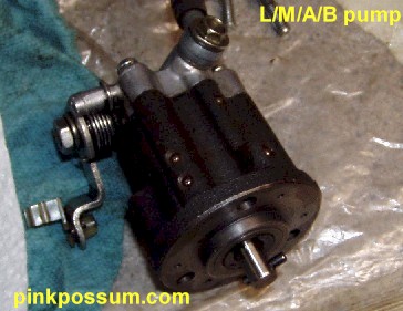
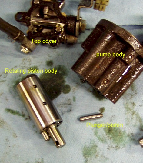
The pump consists of three major assemblies seen in the picture above.
Top Cover
At the top is an aluminum cover which contains the bleed screw, oil intake and actuator arm. the actuator arm is moved either by a throttle cable (early models) or a by a linkage rod (CV carbs). As the throttle is opened, the arm is "pulled" which makes it rotate in a counter clockwise direction. The arm rotates on a steel shaft which is ground into an eccentric in the center.
Pump Body
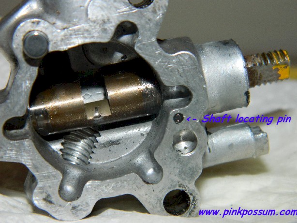
The pump body contains the passageways through which oil is pumped in measured amounts through to six outlets - three for the intake ports and three to the crankshaft main bearings.
Pump Valve
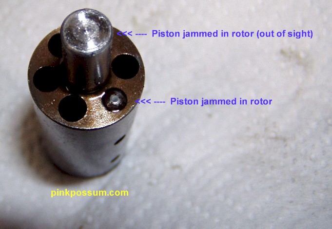
The third sub assembly is the pump valve as it's called by Suzuki. It's a hardened ground steel cylinder containing six ports or passageways and looks much like the revolver of an old six gun. Into two of those chambers are pistons (one short and one long) or plungers in Suzuki nomenclature. It is referred to here as the ROTOR, and the plungers as PISTONS.
The top of the Rotor (pump valve) is ground into face cam with two flat lobes and in the center at the top is a guide pin that locates the top of the rotor into the actuating shaft in the top cover.
Which pump do I have and does it matter?
There are 4 different pumps with 2 designs of lever arm, 2 designs of top covers and three Rotor designs. Which is which is easy to determine.
J 1972 pumps
Early model pumps contained three plungers rather than the two in later pump assemblies ( two long pistons and 1 short one). The additional plunger was for suction, to pull oil from the oil tank. That was found to be unnecessary and in fact all oil pumps are capable of collapsing the oil tank if the breather is blocked.
The actuating arm was also different to later models. It was operated by a 4th cable in the throttle cable assembly where later models with CV carbs used an actuating arm connected to the butterfly shaft. The actuating arm has teh number 310 stamped into it, indicating that it is a -130xx type pump..
Suzuki list only one pump for J and K models, part number 16100-31002. It is probably safe to assume that the change came relatively early in production and that Suzuki may not have offered a three plunger pump through the parts and service operation. Presumably the earlier pump would have carried an earlier number such as 16100-31001 or 16100-31000.
K 1973 pumps
Suzuki amended the pump design and deleted the third plunger. That entailed a change to the main rotor. All other parts remained the same. That is the pump shown in parts lists as 16100-31002.
L-M 1974-5 pumps
The lever arm was changed from cable actuated to one which was actuated by a pull rod from the new CV style BS40 mikuni carbs. All other parts including the rotor, main cast iron body and top cover were carryover parts. That design of pump is 16100-31201. Easily differentiated from the J-K pump by the lever arm which is stamped 312 to reflect the part number change to -312xx.
A-B 1976-7 pumps
The A model of 1976 saw a new oil pump with part number 16100-31202. Externally very similar to the L-M -31201 pump but it had lost the hardened pin in the top cover and had a revised, taller rotor. The body, plungers and springs, actuating arm and shaft are all carryover parts. Why the design was changed is not clear. One less part and a couple of machining and assembly operations were eliminated, so maybe it was a cost reduction exercise or maybe they had durability issues, we have no way of knowing. If we find out, this will be updated.
Does it matter which pump I fit?
No. Any pump can be fitted to any year of engine simply by changing the lever arm to the appropriate type. It is probably better to avoid the very early 3 plunger pumps. The main cast iron pump body and top cover casting remained the same throughout, so all pumps are the same physical height and pump the same amount of oil.


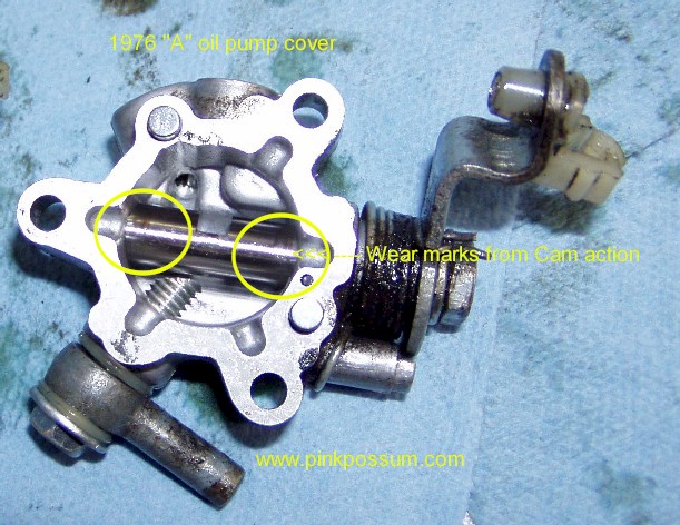
1974 L model pump uses a hardened pin in the top cover
1976 A model pump dispenses with the pin and the valve body face cam acts upon the actuator shaft

The Pump Valve on the left is visibly lower than the 76 on the right. The face can rubs on that hardened pin, whereas in the taller 76, the pump valve face cam rides directly on the actuator shaft
How does it work?
The pump is driven through a train of gears at 1 revolution per 62 engine revolutions. As it rotates, the plungers (pistons) on springs in the valve body cause the valve body to press upwards against the top cover. As the valve body rotates, the face cam contacts the hardened pin in the top cover and that forces the valve body downwards expelling oil from a port in the lower face.
The valve body (rotor) is the part that rises and falls. The plungers (pistons do not rise and fall in their bores, but the bores move relative to the pistons. Anyone familiar with an aero engine swash plate pump should feel right at home in a GT750 oil pump.
When the as throttle is opened, the actuating arm on top is rotated which allows the valve body to rise higher and creates a longer stroke and more oil is expelled .

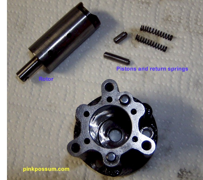
Rotor and pistons
What goes wrong
As a rule, very little. In normal operation all the pump components are fully immersed in oil. In addition, the housing is cast iron which is self lubricating up to a point. Run the pump dry though and the pump may be damaged before the pistons and crank. Oil leaks are not uncommon and are messy to fix but not very difficult. Shafts do wear though and the most common problem is people trying to force close the pump. When stopped, the lever arm only returns to the CLOSED position once per every few revolutions. Worried owners often see that the arm did not fully return and tweak the throttle until they manage to force it back. That must be why Suzuki covered the pump - so that owners would not be worried.
Another mode of failure is the end plate in the main body becomes displaced and that significantly reduces pump output. In one pump we we received recently the end plate had moved 1.5mm and that would reduce output to the main bearings to zero. The good news is that bike would not have smoked. The bad news is obvious - it would have failed catastrophically.
One mode of failure seen from time to time are sticky pistons. If the pump has ingested foreign material or has passed a mix of say castor based oil and regular petroleum based oil, the pistons may be stuck in the rotor. This is most likely to occur on barn finds or on pumps removed and left on a shelf at a breakers yard. To fix sticky pistons, they must be removed and cleaned thoroughly or engine failure will quickly follow.
This pump was purchased recently from that well known on line auction site very cheaply, but if it had been fitted without a full checkout, it would have resulted in catastrophe.
How can it be checked?
In theory, the pump could be set up on a test jig and run at a fixed speed while output is checked. That would be a really good way to know if it's working to specifications, but a lengthy process for one pump.
A simpler way is to first place a pin through the hole in the lower part of the rotor shaft and rotate the rotor. With the actuating arm at in the IDLE position, resistance should be felt as the rotor is rotated. It should be possible to feel the cam effect every 180 degrees as it rises and falls slightly.
Then move the actuating arm to the FULL THROTTLE position, and the rotor should now rise and fall considerably further. It's odd to see the whole shaft rise and fall, but that's why the drive shaft is slotted - to allow the drive pin to move in the slot.
If that doesn't happen, the pump MUST be stripped and cleaned. If it passes that simple test, the next test is to see if it actually pumps oil. Before the pump is fitted, prime the oil lines with a syringe filled with oil a contrasting color to the oil in the oil tank. Two stroke oils are often deep red or blue or purple, so use clear/gold 4 stroke oil to prime the lines.
Fit the pump, taking care to avoid kinking the feed line and then bleed the pump. Start the engine and either hold the actuating arm wide open or take the bike for a short run.
-
If all six lines are now full of colored oil and the gold oil has been purged, great everything is fine.
-
If one set of three lines (crank or intakes) are purged and 3 are still full of contrast, one of the pistons is stuck.
-
If one or more lines are not purged, the problem is a blocked line or damaged or stuck valve at the end of the oil lines.
Top Cover
The top cover, like the rest of the pump, is not designed to be serviced by the owner.
In theory, that makes sense, but in the real world where some of use are trying to keep these ancient relics fully operational, there has to be a way to service the pump top cover.
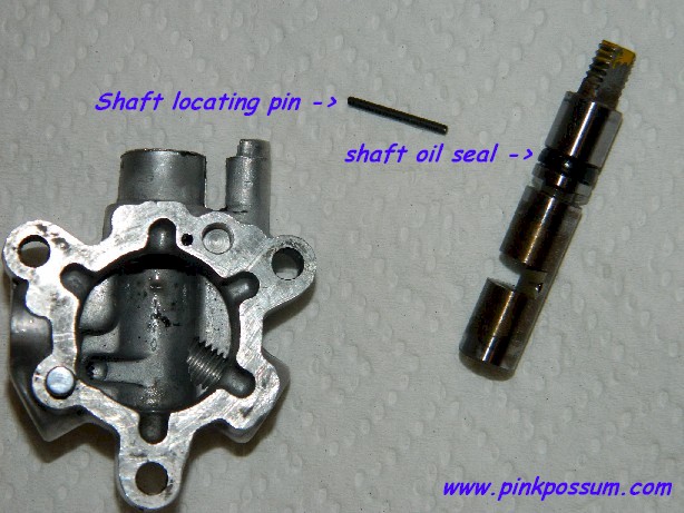
The top cover consists of a shaft with lever plus locating hardware (washers, springs and a loctited nut).
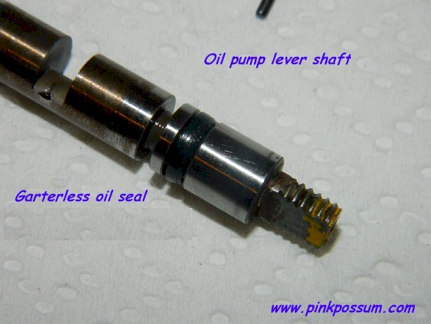
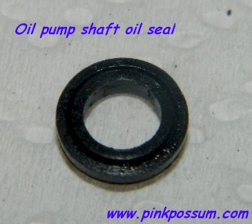
The adjusting shaft is located by a small 1.5mm diameter steel pin. There is also a small oil seal set into the shaft to prevent leakage along the shaft.
Old pumps often leak a little along the shaft, and when they do, the only solution is to strip the top cover and replace the oil seal.
Unfortunately Suzuki never supplied parts for the pump.
Oil seals, top cover gaskets and other components were never made available by Suzuki.